In continuation of my first post in this series, I will be detailing my build process and the various challenges along the way. Overall, it took me 2 nights for building, 1 night of troubleshooting Windows, and 1 night of minor adjustments. If my last components (fans and RAM) arrived on the weekend instead of Monday, I would have done it all in one go. Work gets in the way but it pays the bills!
Day 1 – Case Preparation and Fans
Since it would be troublesome to remove the stock fans after installing components, I decided first to knock out all of the fans including the CPU cooler radiator installation. The Corsair Vengeance C70 case comes with 3x 120mm stock Corsair fans. They are nothing special but would have been sufficient if I didn’t buy additional fans. 1 fan was mounted as rear exhaust, and the other two were mounted behind the storage drive bays as intake (pulling air through the bays).
My overall airflow plan was as follows:
- 1x stock Corsair fan as rear exhaust
- 2x AF120 Corsair red LED fans as side window intake
- 2x SP120 Corsair red LED fans as front intake (in front of the drive bays, so pushing air through the bays)
- Corsair H100i cooler (radiator + 2x stock SP120 fans) on the top as exhaust
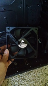
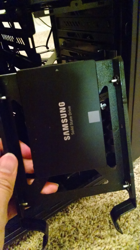
First, I had to remove the 2x stock fans behind the drive bays. Below is a picture of one of the stock fans I removed.
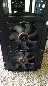
Second, I had to figure out how to install the 2x SP120 red LED fans onto the front. I thought I would need to remove the drive bays, but that didn’t seem to be working out. I then switched to popping off the front panel of the case (no screws, just tabs that needed to be depressed) and then mounting the two fans to the front. There’s a filter on the front panel, so the intake air should be clean. I chose SP120 fans at this location because the drive bays provide an obstruction to the air flow. Higher static pressure fans can push air better through obstructions. I used the provided case’s long fan screws for mounting. Both fans connect up to a 4 pin splitter I bought, so they will be controlled by one fan header on the motherboard. The fans are actually 3 pins, but the 4 pin splitter looked nice.
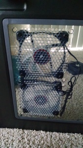
Next up were the side window intake fans. I chose 2x AF120 fans since the air flow would not be obstructed here. I used the screws that came with the fans this time around. They are short but do the job. The 120mm fan screw holes on the window also have fan rubber mounts, which help to limit vibration. The installation for these fans went fairly quick with no issues. I used another splitter for those too.
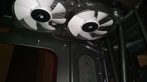
Last, but certainly not least, was the Corsair H100i CPU cooler. The cooler requires a bit more effort since you need to assemble the fans onto the radiator first and then mount the radiator into the case. The cooler came with decent instructions. I decided to use the stock SP120s that came with the cooler. The fans connect up to a 4-pin splitter that goes into the Corsair CPU cooler hub. I could have connected the fans to a motherboard fan header, but then the Corsair Link software would not be able to control the fan speeds. Here’s a picture with the fans installed onto the radiator.
Mounting the radiator took some time. Another set of hands to line up the holes and keep the radiator from moving would have helped! There are a total of 8 mounting screws. The top of my C70 case already had rubber mounts for the holes I was planning to use. Once I got everything lined up and screwed in, here’s the end result of my labor!
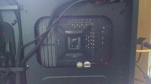
I thought for a while if I was mounting this cooler in the correct orientation. I could have flipped it 180 degrees with the tubing towards the back. The main problem I foresaw at the time would be that I would need to twist the tubing to get the Corsair logo to face the correct orientation. These small decisions eventually have consequences down the road. This one was minor, but I will detail it when I run into it! That was all of my work for Day 1. It was a Monday, so I was ready to go to sleep.
Day 2 – Finishing the Build
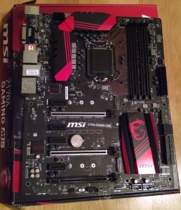
With the case and fans ready to go, I was ready to move onto the motherboard. I watched a few build videos, and the majority of them install the CPU and then the RAM before placing the motherboard into the case. The CPU installation was the scariest part of the build! You are holding a $360 chip! My MSI z170 Gaming M5 motherboard had standard CPU installation instructions. Turn back the lever, remove the CPU cover on the mobo, place the CPU onto the socket, close the bracket, and then bring back the lever to secure it into place.
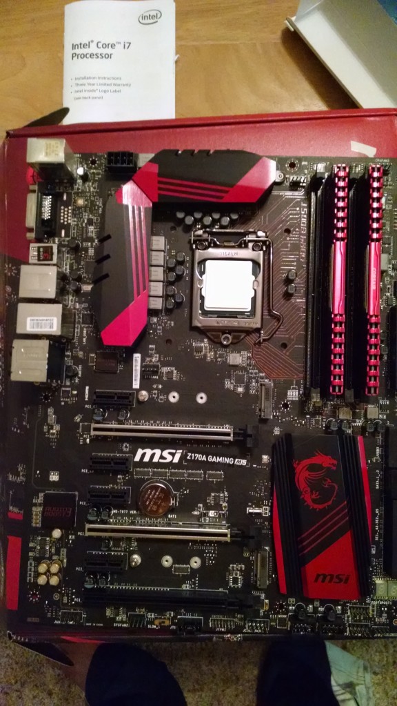
Seating the CPU was rather scary. I read warnings about not touching the bottom of the CPU (don’t want to mess up the pins) and about not touching the top in order to reduce the amount of dirt that gets on the CPU for cooler installation later on. You have to hold the CPU on its sides and then line up the CPU with the socket (there’s an arrow on the bottom left corner that tells you if you have the correct orientation). The first time around, I didn’t seat it correctly. It twisted a little bit and was not lined up correctly at all! I had to very carefully grab the CPU on its sides, lift it up, and gently seat it correctly. I got it in on the 2nd try. I gently pushed horizontally on the chip to make sure it was indeed in the socket this time. The second scare with the CPU installation was locking it into place. I felt like I was going to break it with how much force is required to bring the lever down into the locked position! The Corsair RAM was easily installed. Just pull the tabs, insert the RAM, and lock it in (should happen automatically). One thing that I had to consult the motherboard manual on was which slots to use for the RAM. I only had 2 modules, so I had to make sure I was taking advantage of the dual channel memory. DIMM slots 2 and 4 were noted for 2 modules. Below is the final picture of the motherboard with CPU and RAM installed.
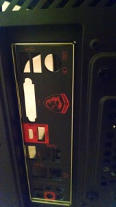
Before I placed the motherboard into my case, I had to install the I/O shield. I read that the shields were notorious for cutting fingers. I managed to avoid that, but I did have trouble getting it perfectly into place. In the end, I think it was OK and all ports are accessible, but maybe it could have been a little better.
Placing the motherboard into the case was another task where an additional set of hands would have helped tremendously. The key to placing the motherboard is having all of the motherboard standoffs lined up and have the I/O ports in the shield. The I/O ports never seemed to line up perfectly, and it may have been an issue with the shield. I can still access all ports and connect to them, but they don’t seem to stick out like I expect they would. I did manage to get all motherboard standoffs lined up. My case has one center standoff that just sticks through the board (no screw), which does help with making sure you have it in correctly. My case had motherboard screws, so I used those to secure it.
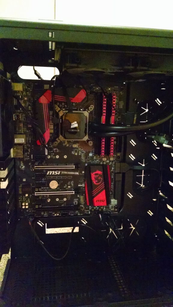
In order to avoid getting any dirt on my CPU, I decided now was the time to mount the cooler onto the CPU. The H100i had decent instructions. I won’t go into details. Basically, you have 4 standoff screws that go near the 4 corners, the mount bracket sits on those screws, and the backplate (other side of the case) has to line up with the standoffs. It was not too hard to figure it all out, but this is one task you shouldn’t consider as minor. A bad cooler mount installation could mean inefficient cooling. Up until this point, I had kept the protective cover of the cooler mount. There’s thermal paste pre-applied on the mount, so no need to apply extra. I made sure everything lined up correctly and all screws were firmly into place.
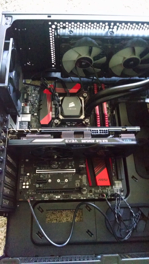
As seen in the cooler mounted picture, I did go ahead and connect the front I/O connectors and cooler connections. Front I/O (Power Switch, Reset Switch, Power LEDs, HD LEDs, Audio, and USB 3.0 header) was not complicated but some of the jumpers were not labeled with positive or negative. The first time around, I did not connect the HD LED and Reset Switch jumpers correctly! Another minor issue but fortunately an easy fix. The Corsair H100i connections were for the fans to the hub, pump to fan header (chose the CPU header), and hub to USB 2.0 header for Corsair Link integration.
Next up was the video card! Fairly easy. I initially did not remove the correct backplate output cover, but that was fixed quickly (silly mistake). Placing the EVGA GTX 970 onto the PCIE slot was not a problem. I did notice the card covers up the chipset heatsink with the dragon, oh well!
Another easy item to install was the ASUS optical DVD drive. I did run into one problem though. The drive would not fit in the first expansion bay at the top because it was long enough where it would hit the CPU cooler tubing. My decision for the cooler orientation did have this one consequence. Fortunately, I just moved the optical drive down one bay with no issues. For this case, the drive was a screwless installation since all you do is slide it from the front, and the clips in the bay snap into place to secure it.
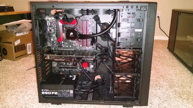
With the main components inside the case, it was time for the EVGA power supply! The power supply was mounted at the bottom with the fan facing down (there’s a filter on the bottom, so clean air again). It was screwed on the back. There were more holes than actual screw holes, which threw me off initially. My power supply has an ECO mode available, where it will not use the fan unless it really is needed. The switch is strangely on the inside, so I flipped it on before I forgot about it. Connecting the power cables was more time consuming than anticipated. I had to feed the cables through the grommets and have them come out at appropriate locations to minimize excess cabling and have a cleaner look. Some of the power cable connections (seen below) are segmented while others are not. The CPU cable confused me for quite a while but I eventually figured out which side goes to the supply and which side goes to the CPU power connection on the board. I had to use two SATA power cables (3 connectors each) since I had to power 4 items: The CPU cooler hub, the ASUS DVD drive, old HDD, and old SSD. My video card supported a 6+8 pin power connector, so I went with that.
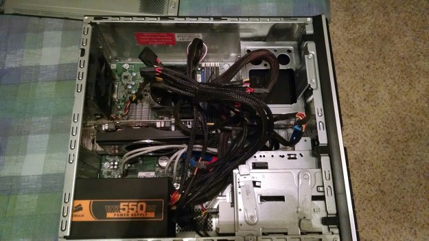
Next up were the storage drives. I decided to move my old drives, a HDD and SSD (with Windows), to my new computer. I had to open up my old computer and grab the drives out! I forgot how messy my old HP computer was on the inside. I replaced the power supply when I added an ATI (AMD) Sapphire Radeon HD 5770 video card, but it was not modular. I have included a few pictures of my old computer to show how must of a mess the inside was.
After I extracted the drives, my new case made installation fairly easy. For the old HDDs, you simply slide out a hard drive tray, flex the tray (with screws already embedded) into the HDD, and then slide the tray back into the drive bay. For the SSD, I had to screw it into a tray and then slide it back into the bay.
What I found troublesome about the storage drive installation was connecting the power and SATA cables. There’s not a lot of room on the other side of the case at the front for any excess cables. The side panel pops out in the middle, but near the drive bay, it tapers. I was running into a lot of vibration problems after I turned on my computer. The SATA cables and power cables were vibrating and transmitting it into the side panel, causing a rattling sound. I had to redo the wiring to stop the vibration from being transmitted into the case. In regards to the SATA cables, my motherboard had 4 that came with it, so I had more than enough. I again consulted my manual to see which port was SATA 1. I wanted my SSD boot drive to be on SATA port 1, but I somehow managed to get ports 1 and 2 switched around (maybe lost track of the cables). Another minor issue easily fixed later on though.
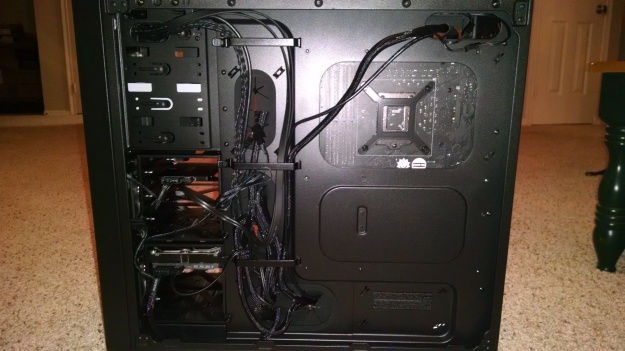
With everything hooked up, I tried to work on cable management. My case has 3 wire brackets on the non-window side that help guide wires along the grommets. The only wires that were significantly off the tracks were the Corsair Link USB 2.0 header, CPU power cable, and fan cables. It doesn’t look as clean as I would like, but it gets the job done. If I get bored one weekend, I may redo the cabling.
I also noticed my case has a little cutout at the bottom right corner where the PSU is located on the other side. I have not figured out exactly what that is for. Perhaps it is an alternate location for a SSD.
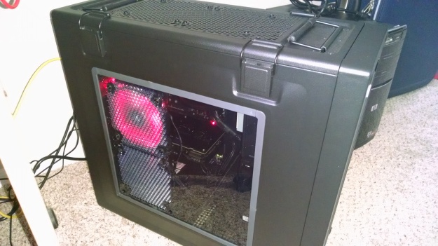
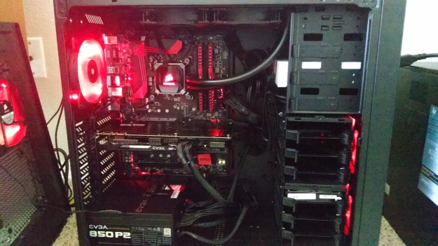
At this point, I had everything in my case, hooked up, but I had not closed it. The non-window panel required a little effort with those cables sticking out, but I got it in fine. The window panel had problems though! I did not realize how tall my video card would be. My top window fan was above the video card, but my bottom fan kept hitting against the video card’s power cables. The power cables are very stiff and there’s very little clearance. If I put in a little more effort, I may have been able to find a solution that kept both side fans, but instead, I went with an easy solution. I removed the bottom window fan, and replaced the stock fan used for rear exhaust with the former window LED fan. Thinking back on my solution, I may have had to remove the bottom side window fan either way when I go SLI, so it was probably the best solution for future upgrading.
The computer build was finally over! Unfortunately, it was 11 PM Tuesday night during the work week, so I decided to wait to turn it on.
Day 3 – It is alive!
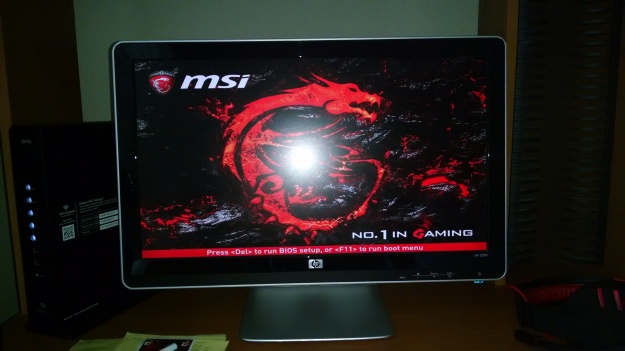
Wednesday at work was rough, knowing I had a computer ready to turn on! When I got off work, I immediately jumped into getting the computer cables in the back connected and finally turning it on for the first time! Seeing the below BIOS splash screen was a relief! The computer POST‘d fine.
I went into BIOS immediately to check the settings. I noticed the memory was running at 2133 MHz, so I enabled the XMP profile, which is a pre-built profile to overclock memory up to its designated rating, which in my case is 3000 MHz. As I mentioned before, I noticed the HD LED didn’t turn on and that the SSD wasn’t on SATA Port 1, but I wanted to boot into Windows before fixing those issues. When I rebooted with the new memory settings, I kept getting an error and had to revert to the old settings. I was a little disappointed, but I decided to go ahead with the boot to Windows.
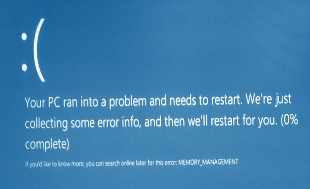
I wanted to use my old drives as is instead of doing a fresh install of Windows. My SSD had my Windows 10 OS on it while my HDD just had my documents on it. I didn’t anticipate the pain that would cause. Windows kept giving me a memory management error.
When I read “memory,” I thought my RAM is bad. However, MSI UEFI-BIOS detected both Corsair modules (just running at slower speeds). After some researching online, I figured out that Windows didn’t have the drivers for my new system, so it was thinking it was the old one instead. The hardware changes were so drastic that it couldn’t boot up. I decided to pop back my storage drives into my old computer, so I could create a Windows 10 flash drive. The Windows 10 repair utility would do the trick I hoped. After creating the Windows 10 flash drive, I booted into it with my new computer (popped the drives back in too), and ran the repair utility a few times. It would run and sometimes do a restart on its own. I wasn’t sure it was working, but I finally did get into Windows!
Windows logged into my account fine, but I noticed it was not activated anymore. It turns out that if you make significant changes to your free upgrade Windows 10 system, it will not recognize the machine. The free upgrades don’t get product keys, so I couldn’t simply enter in the key. I talked to Windows tech support that night, but I was informed that I would need to wait in the morning to get the activation center to take care of my problem. In the mean time, I went ahead and installed all of the drivers and software for my new components. MSI has a lot of software that comes with their motherboards. One cool option for gamers is one free year of Xsplit Gamecaster premium subscription. Corsair Link software allowed me to control my CPU cooler directly and change the LED lighting on it too.
Despite the Windows problems, I was pretty happy that the system booted up the first time!
Day 4 – Activating Windows, Minor Fixes, and Gaming!
Having got Windows finally working on Wednesday, Thursday was dedicated to the remaining issues. I called Windows in the morning, and I got them to activate my Windows manually after verifying my Windows 7 key! Very quick and easy too. I was told that I would need to call them again if I wanted to do a fresh install.
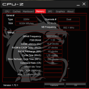
My memory was still running at lower speeds. I tried a manual overclock in BIOS, but it would not work at 3000 MHz. Bumping it down to 2800 MHz did work though. I was still not satisfied, so later I found out that outdated BIOS is usually the main issue with XMP profiles not working. I flashed my BIOS with the latest version (1.4 versus 1.0) using M-Flash and XMP finally worked! The XMP profile also did a slight overclock on my CPU from 4.0 GHz to 4.2 GHz. Here’s the CPU-Z snapshot as proof!
In addition to these changes, I fixed the jumpers for the HD LED and Reset Switch (haven’t used that one yet). I eliminated the vibration problem with my storage drive cables. I ran SWTOR for the first time on the machine, and everything was pretty! I feel my monitor is holding me back with 1600×900 resolution though. I’m usually at very high FPS (80 to 100 on max settings) with less than 50% CPU load.
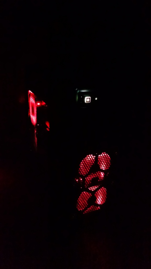
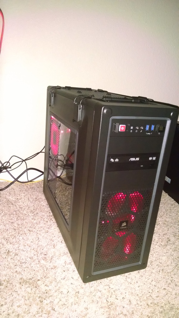
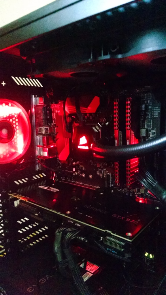
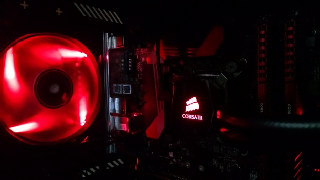
The final post in this series will focus on benchmarking and overclocking (CPU and video card). I will end this blog post with pictures of my final build. The red LEDs really make it stand out! I’m looking for names for my PC. I thought Kylo Ren would be appropriate with Episode VII coming out this year.

